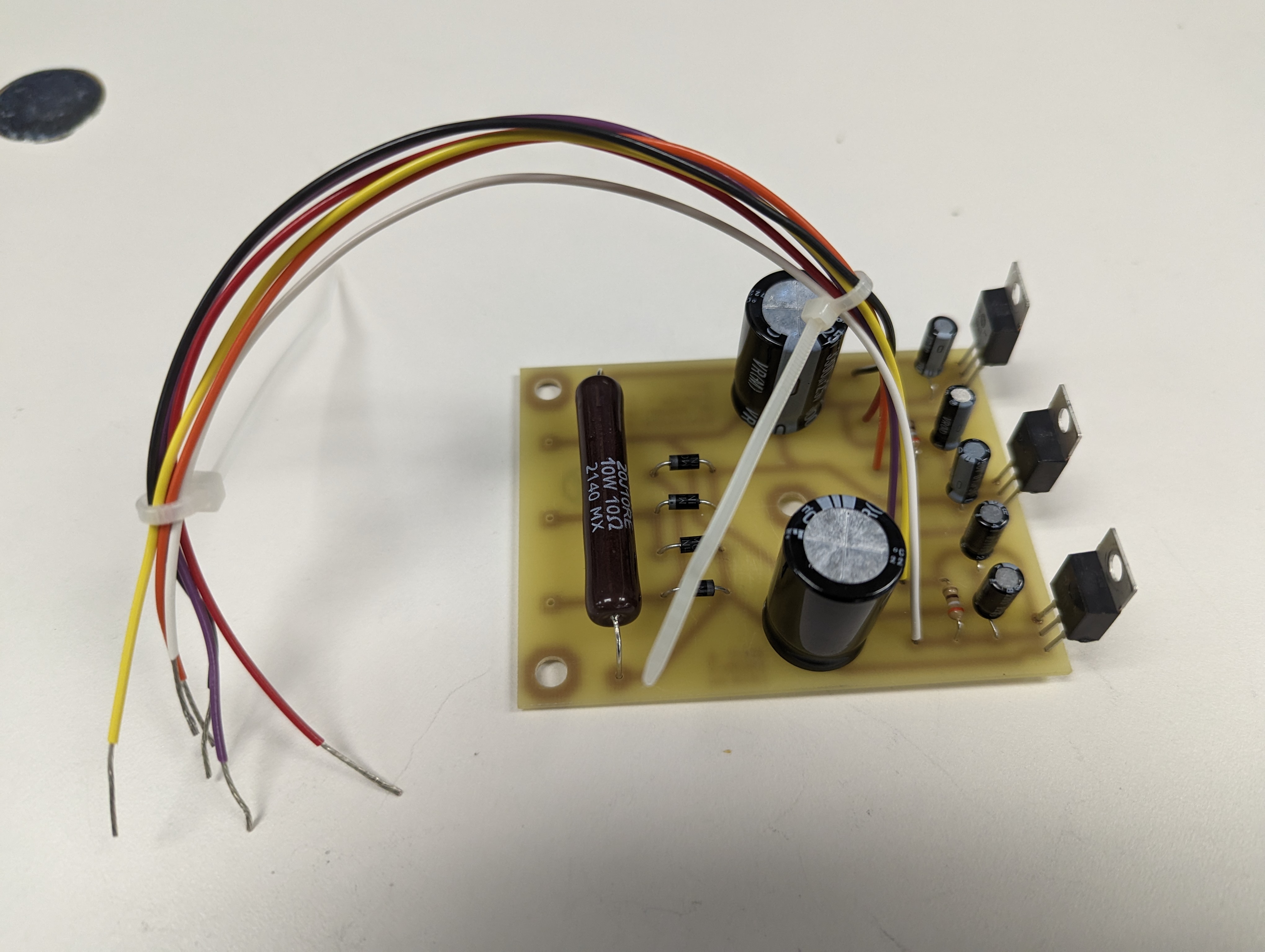
Printed Circuit Board With Components
This is the PCB for a DC power supply after I had finished soldering all the components to it.
I am an Electrical and Computer Engineering Technology student at BCIT, who's also interested in programming and writing.
This is the PCB for a DC power supply after I had finished soldering all the components to it.
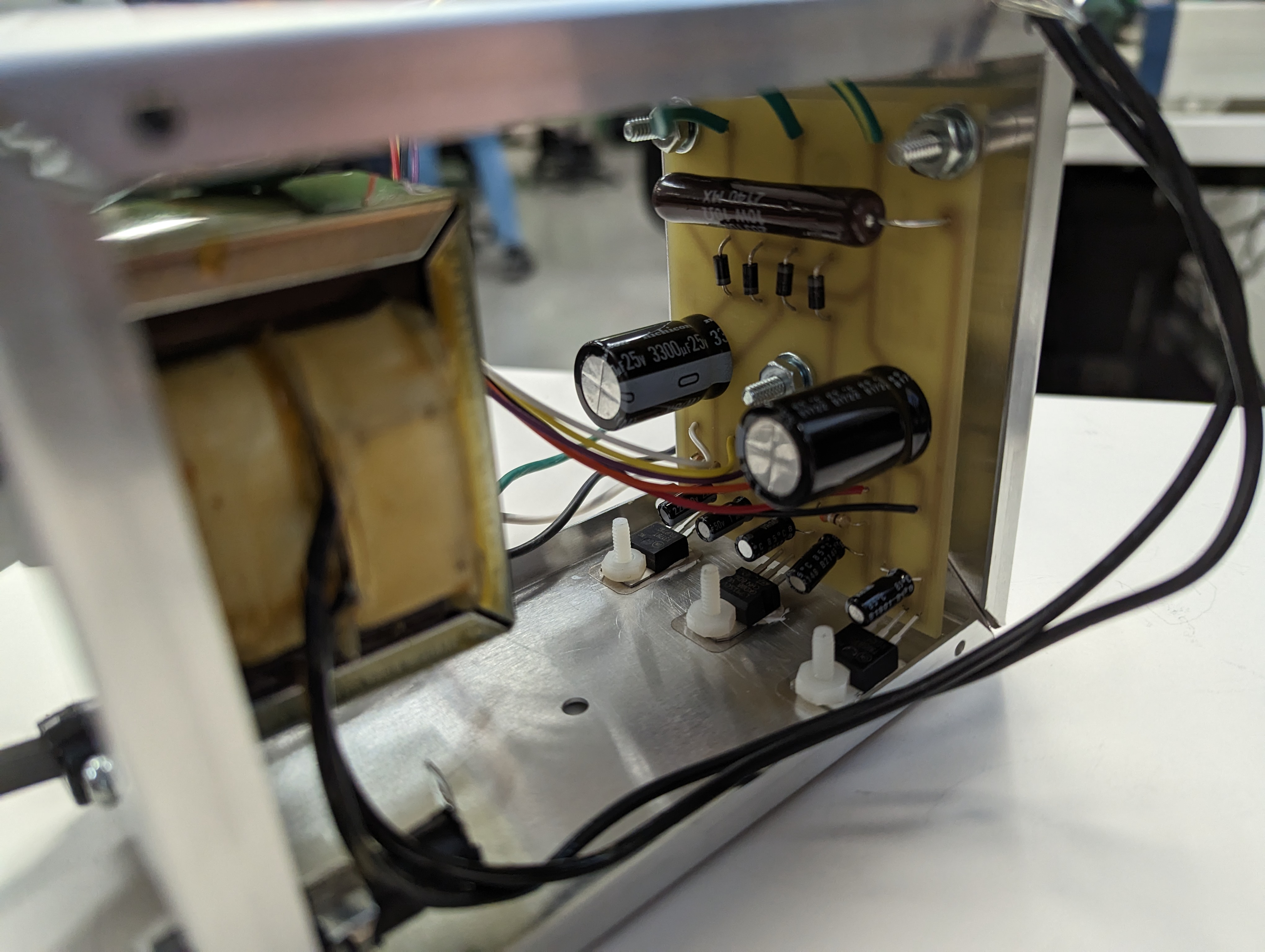
This is the transformer and the PCB after being installed into the chassis of the DC power supply.
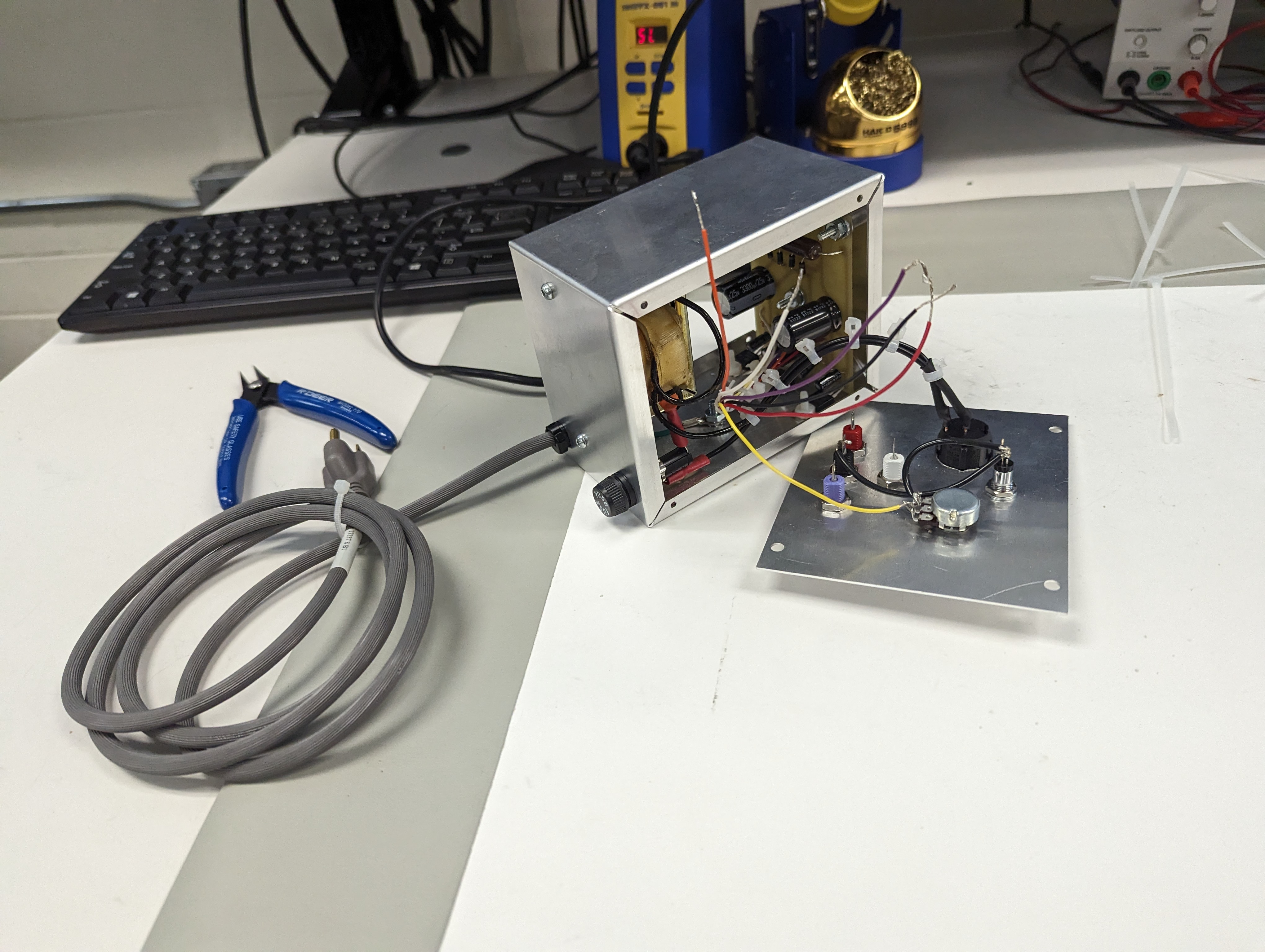
This picture was taken part way through soldering the DC wires to the back of the face plate.
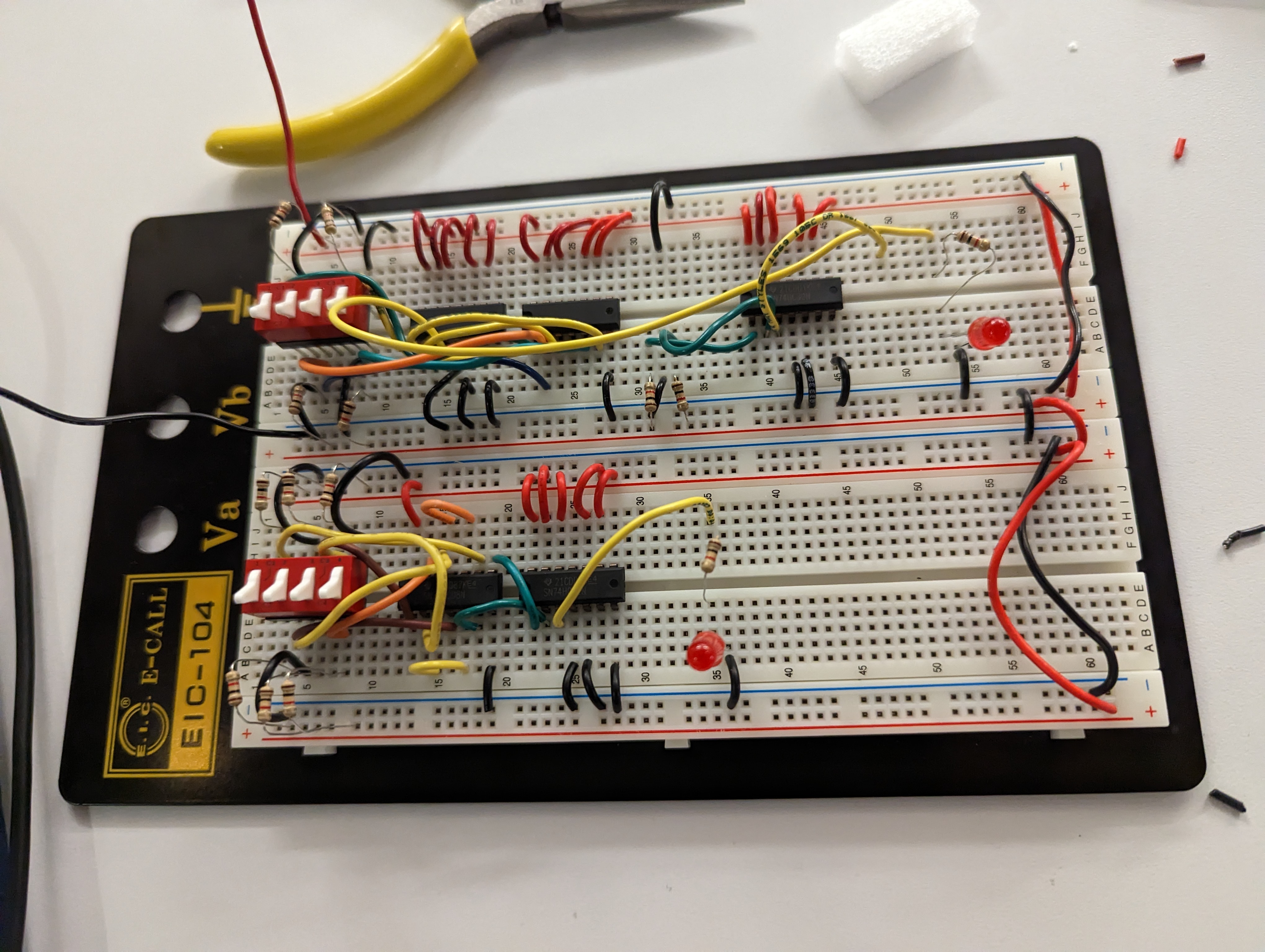
An early digital techniques lab project, with three circuits that run on grayhill switches and give an LED output. (Rightmost circuit switch is removed in this photo)
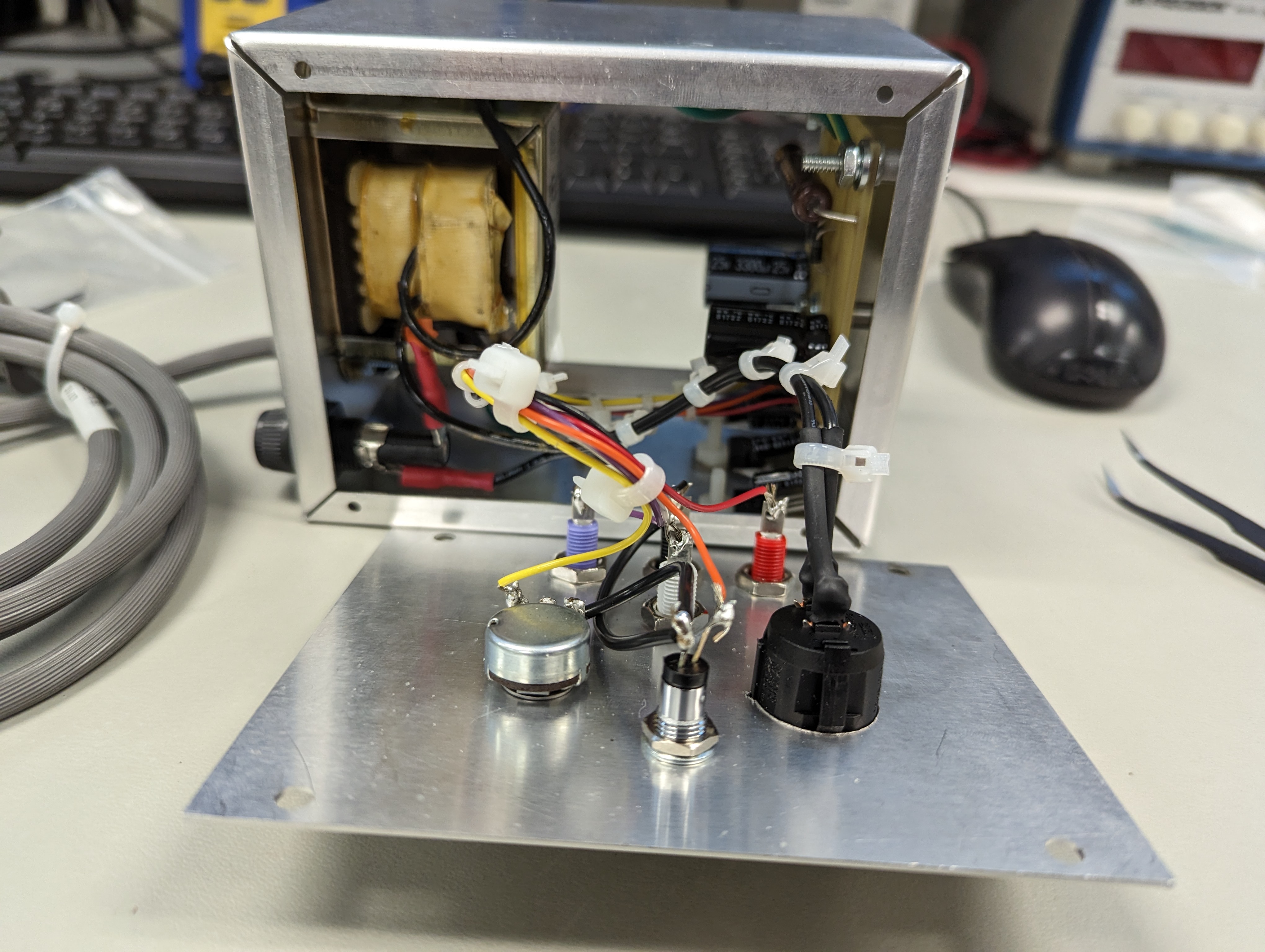
After soldering all the wires to the appropriate faceplate functions, and using cable ties to make it look neat.
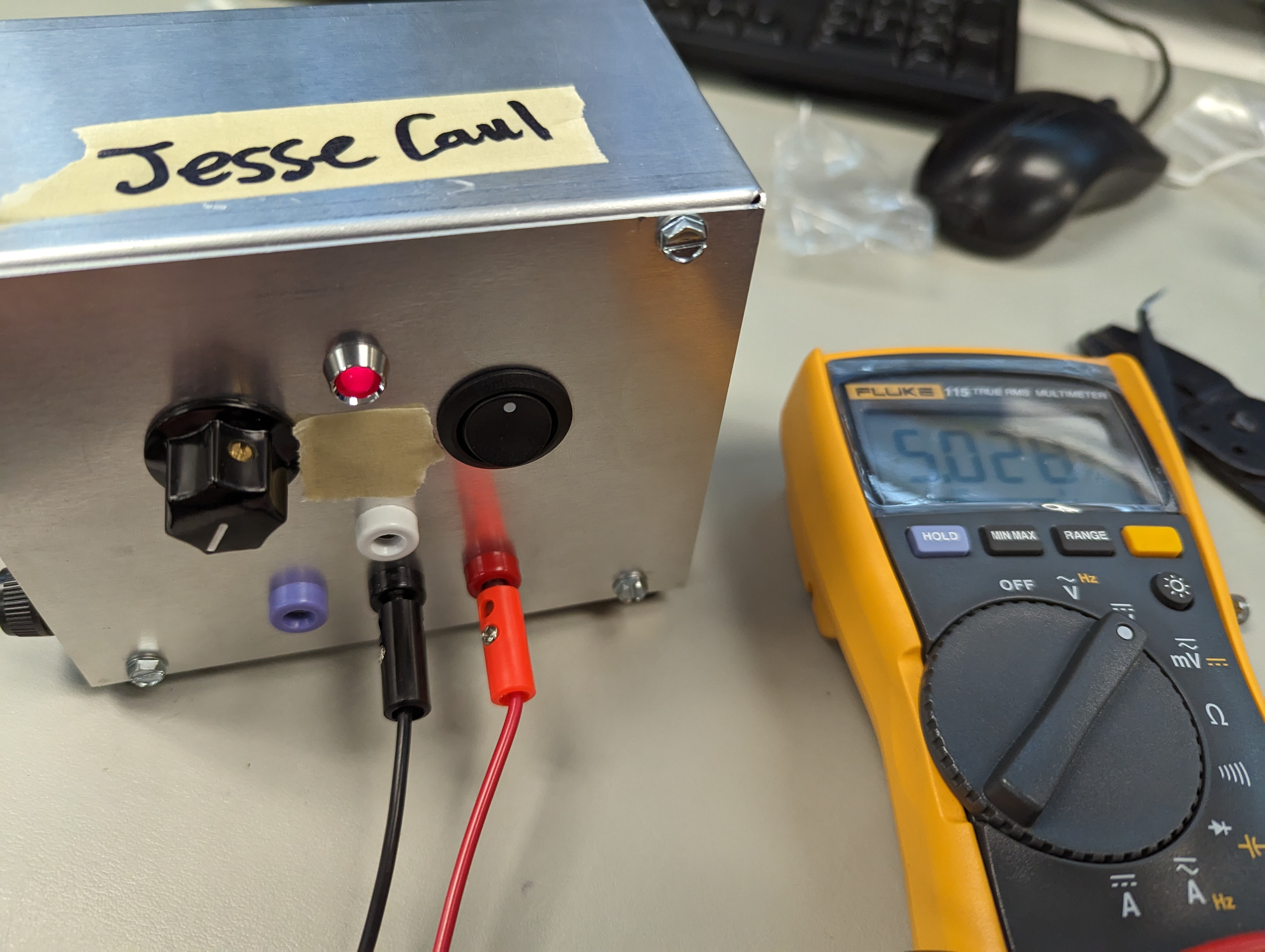
After screwing on the backplate and faceplate, but before adding the -15V, variable 0-15V, +5V, and common port labels.
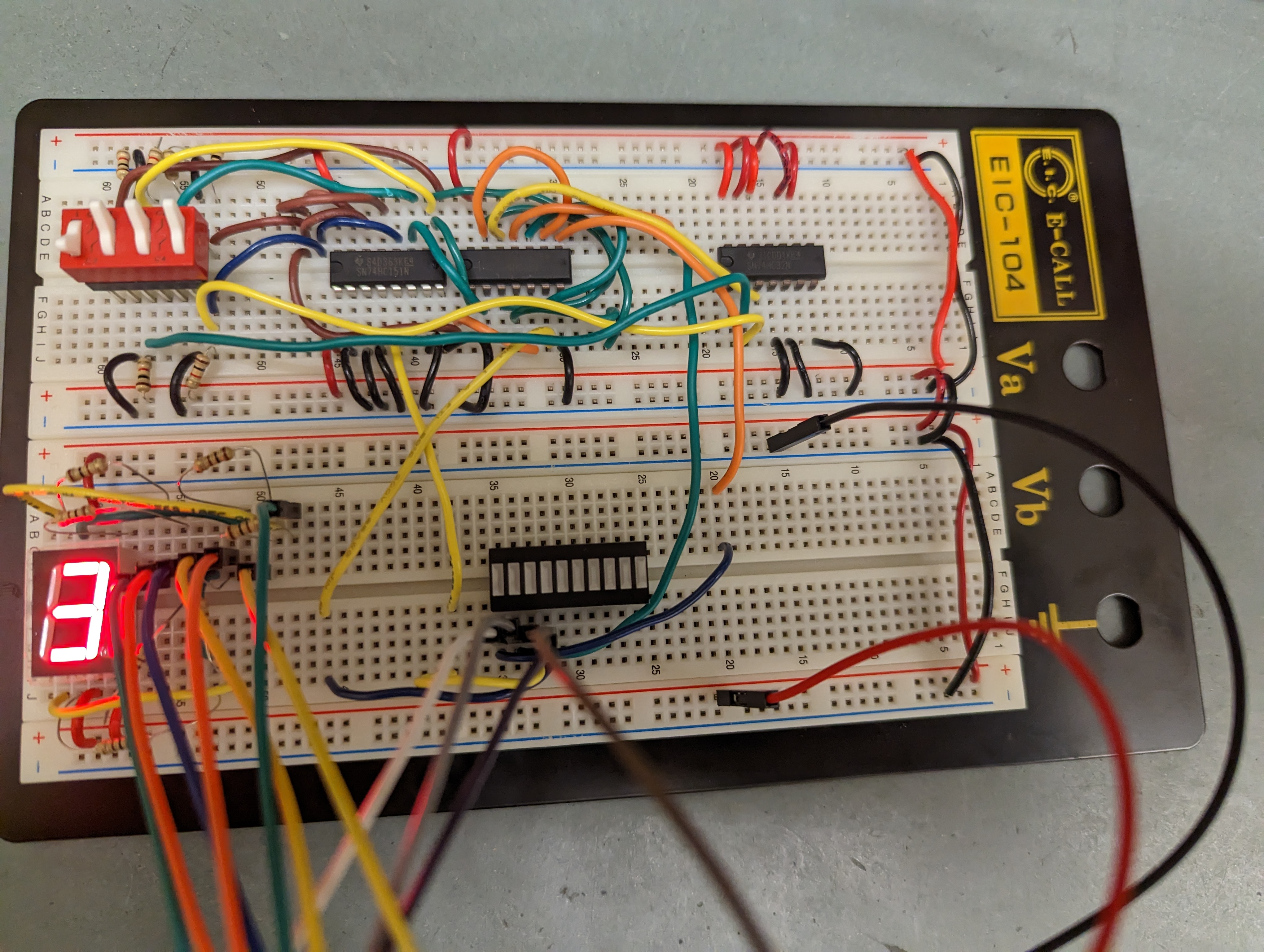
Circuit that takes 2 2-bit binary numbers as input from the switch and multiplies them together. The wiring could be neater, but there were some pretty harsh time constraints.
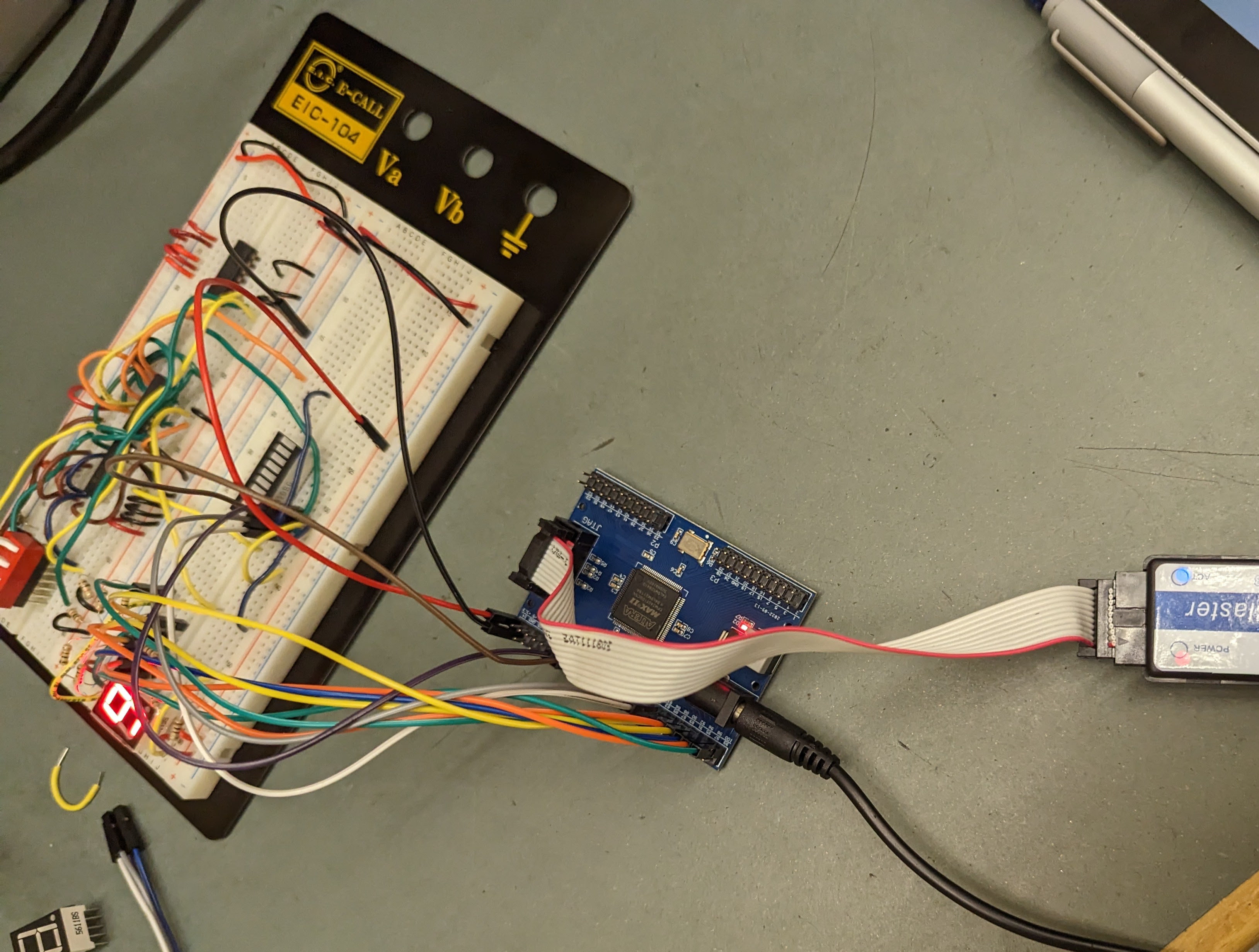
2-bit multiplier circuit with PLD shown. The PLD is programmed in AHDL to take the binary output of the circuit and turn on the appropriate LEDs on the 7-segment display.